Content
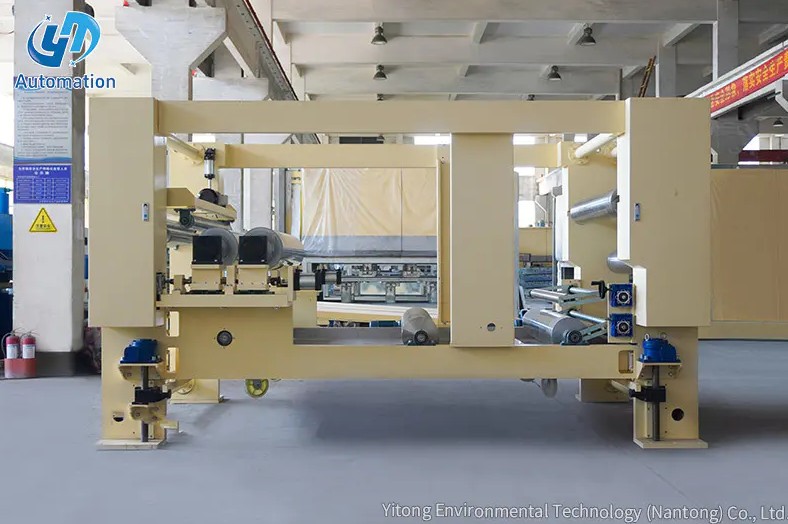
A rotary unwinder is a web-handling machine that continuously feeds a roll of material — such as paper, film, foil, fabric, or nonwoven — into a downstream converting, printing, coating, or laminating process at a controlled speed and tension. It rotates the parent roll as material is consumed, maintaining a steady, consistent web feed without interruption. Unlike manual or static unwind stands, a rotary unwinder integrates active tension control and, in automated configurations, splicing or roll-change capability that allows production to continue uninterrupted when one roll is exhausted. It is a fundamental piece of equipment in any continuous-web manufacturing line.
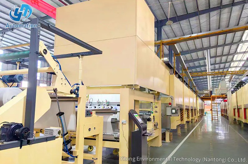
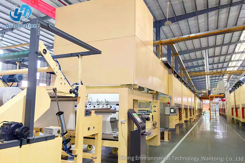
In any web-based manufacturing process — whether printing, slitting, laminating, coating, embossing, or converting — the raw material arrives as a wound roll. The rotary unwinder's job is to translate that wound roll into a moving flat web travelling at the correct speed and tension into the machine's processing section.
The three core functions a rotary unwinder performs are:
A rotary unwinder is composed of several integrated subsystems, each contributing to stable, consistent web delivery. Understanding these components helps operators and engineers specify, commission, and maintain the equipment correctly.
The frame is the structural foundation of the unwinder, supporting the full weight of a loaded parent roll — which can range from 200 kg to several tonnes depending on the material width and roll diameter. Heavy-duty frames are fabricated from high-tensile steel plate (such as A3 structural steel) welded into a rigid box section or portal structure. Rigidity is critical: frame deflection under load would alter the geometry of the web path and cause tension variation and tracking errors.
The reel support — also called the unwind arbor or mandrel assembly — holds the core of the parent roll and transmits rotational force to it. Safety clamp-type supports secure the roll core firmly during high-speed rotation, preventing axial or radial slippage that could cause the roll to drop or the web to break. A Φ76 mm scroll release shaft is a common standard size in paper and film unwinding applications, matching the 76 mm (3-inch) paper core widely used in the converting industry. Expanding chucks or pneumatic collets grip the core from inside, allowing fast and secure roll changeovers.
The tension control system is the most technically sophisticated subsystem of the rotary unwinder. Its purpose is to automatically maintain the web at a pre-set tension level regardless of changes in roll diameter, line speed, or process acceleration and deceleration.
Tension control is achieved through one or a combination of the following approaches:
Parent rolls are never wound with perfect lateral uniformity — edge wander, core telescoping, and material width variation cause the web to drift laterally as it unwinds. A web guide system corrects this by sensing the web edge or centreline position and moving the unwind stand or a steering roller to re-centre the web. Edge sensors using ultrasonic, optical, or contrast-sensing technology detect web position to an accuracy of ±0.1–0.5 mm, driving actuators that maintain registration throughout the roll.
Loading a heavy parent roll onto the unwind shaft safely and quickly is a critical operational requirement. Roll loading mechanisms range from simple manual lift systems with hoist attachment points on the frame, through hydraulic or electric lift tables that raise the roll to shaft height without manual lifting, to fully automatic roll changers that pick up new rolls from floor cradles and position them on the shaft under machine control. The choice of loading mechanism depends on roll weight, changeover frequency, and available operator headcount.
Rotary unwinders are available in two fundamental configurations that differ in their approach to roll changeover — the transition from one exhausted roll to the next.
The simplest configuration holds one roll at a time. When the roll is exhausted, the line must stop, the empty core is removed, a new roll is loaded, and the web is manually or semi-automatically threaded through the machine before production resumes. Single-station unwinders are lower in cost, simpler to maintain, and appropriate for operations where roll change time is acceptable relative to the production run length — typically in slower-speed lines, short-run converting, or materials too delicate for flying splicing.
A turret unwinder holds two or more roll positions on a rotating arm or carousel. While the active roll unwinds, the next roll is pre-loaded and prepared on a standby position. As the active roll approaches exhaustion, the turret rotates to bring the new roll into the active position and an automatic or semi-automatic splice is made — joining the tail of the expiring web to the leading edge of the new roll without stopping the line.
Turret unwinders enable zero-speed splicing (the web is briefly stopped at the splice point while the line runs from an accumulator) or flying splicing (the splice is made at full running speed using adhesive tabs on the new roll core). Flying splice turret unwinders are essential in high-speed paper, film, and flexible packaging lines where any stop produces scrap and disrupts downstream processes that cannot tolerate interruption.
When specifying a rotary unwinder for a particular application, the following parameters must be defined to ensure the machine is correctly sized and configured:
| Parameter | Typical Range | Significance |
|---|---|---|
| Maximum roll diameter | 400 mm – 2,500 mm | Determines frame height and roll loading requirements |
| Maximum roll weight | 50 kg – 5,000 kg+ | Determines frame structural rating and bearing specification |
| Web width | 100 mm – 5,000 mm | Determines shaft length, guide system width, and frame span |
| Maximum line speed | 10 m/min – 800+ m/min | Determines drive system power and tension control response speed |
| Core diameter | 38 mm, 76 mm, 152 mm (1.5", 3", 6") | Determines shaft and chuck specification |
| Tension range | 1 N – 5,000 N | Determines brake/drive sizing and load cell specification |
| Tension control accuracy | ±1% – ±5% of set point | Determines system suitability for sensitive materials |
Rotary unwinders are present wherever a wound roll of material is the starting point for a continuous manufacturing or converting process. The range of industries and specific applications is broad:
A static unwind stand — the simplest form of roll holder — supports the roll on an axle and allows it to rotate freely as the web is pulled off by a downstream drive. While sufficient for very slow-speed or low-tension applications, a static stand provides no tension control and is unsuitable for any process that requires consistent web tension, controlled deceleration, or high-speed operation.
| Feature | Static Unwind Stand | Rotary Unwinder |
|---|---|---|
| Tension control | None (free rotation) | Automatic, closed-loop |
| Suitable line speed | Up to ~20 m/min | Up to 800+ m/min |
| Web guiding | Manual adjustment only | Automatic edge/line guide |
| Roll changeover | Manual stop required | Manual, semi-auto, or flying splice |
| Suitable materials | Heavy, forgiving substrates | Any web material |
| Capital cost | Very low | Medium to high |
Rotary unwinder performance issues typically trace back to a small set of recurring causes. Addressing these proactively through machine setup and maintenance prevents the majority of web breaks, tension upsets, and registration errors in downstream processes.
Tension spikes during acceleration or deceleration, and progressive tension increase as roll diameter decreases, are the primary causes of web breaks. Prevention measures include verifying that the tension control system's taper tension compensation is correctly calibrated for the material's modulus, checking that dancer roll air pressure or load cell zeroing is within specification, and confirming that the brake or drive responds within the required time constant for the line speed in use.
Lateral web drift causes edges to contact machine structure, producing edge damage, dust generation, and registration errors. Web guide systems require sensor calibration checks at each roll change to confirm that the guide reference point matches the actual required web centreline or edge position. Roll eccentricity — where the roll core is not concentric with the wound roll OD — produces a periodic lateral oscillation that may exceed the web guide's correction bandwidth, causing intermittent drift that the guide cannot fully suppress.
Incorrect roll loading — particularly rolls loaded off-centre or with the chuck not fully engaged — causes shaft deflection under load, uneven tension distribution across the web width, and potential roll drop at speed. Safety clamp-type supports with positive engagement confirmation (such as a proximity sensor verifying chuck extension) significantly reduce this risk in high-speed production environments.
Rotary unwinders are mechanically robust but require regular maintenance to sustain accurate tension control and web guiding performance over their service life.
Contact Us
Recommended Products
Let’s Get In
Touch
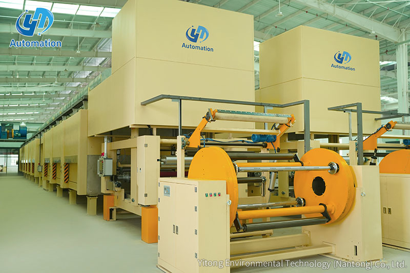
Yitong Environmental Technology (Nantong) Co., Ltd is a manufacturer specializing in impregnation equipment.


Contact Us
Phone: 13073202297 / 13023568111
Email: [email protected] / [email protected]
Add:No.369, Nanhai Road, Tongzhou Bay, Jiangsu, China
 English
 中文简体
中文简体
 русский
 عربى
عربى