Content
A secondary coating machine is a specialized piece of industrial equipment used in the optical fiber cable manufacturing process to apply a protective polymer layer — known as the secondary coating or loose tube — over optical fibers or fiber ribbons. This layer shields the delicate glass fibers from mechanical stress, moisture, and environmental damage, making it one of the most critical stages in producing reliable fiber optic cables. In short, the secondary coating machine transforms fragile bare fibers into durable, deployable cable components ready for further jacketing and installation.
Beyond simple protection, the secondary coating process precisely controls buffer tube diameter, wall thickness, and gel-filling density — all of which directly affect the cable's optical transmission performance and long-term durability in the field.
In a typical fiber optic cable manufacturing line, bare optical fibers first undergo primary coating (acrylate coating applied directly on the glass) and then enter the secondary coating stage. The secondary coating machine extrudes a thermoplastic material — most commonly PBT (polybutylene terephthalate), PP (polypropylene), or HDPE (high-density polyethylene) — around one or more fibers to form a buffer tube.
This process typically involves three simultaneous operations:
The result is a loose-tube buffer — the fundamental building block used in stranded, slotted-core, and ribbon fiber cable designs deployed in telecommunications networks worldwide.
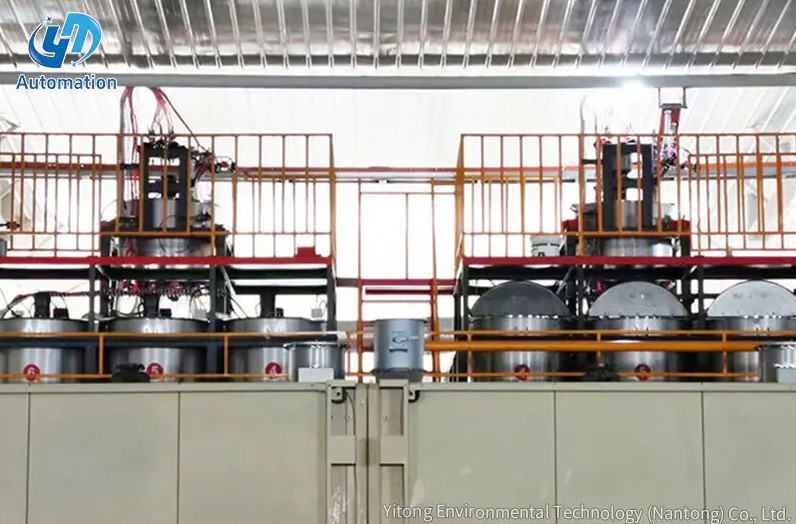
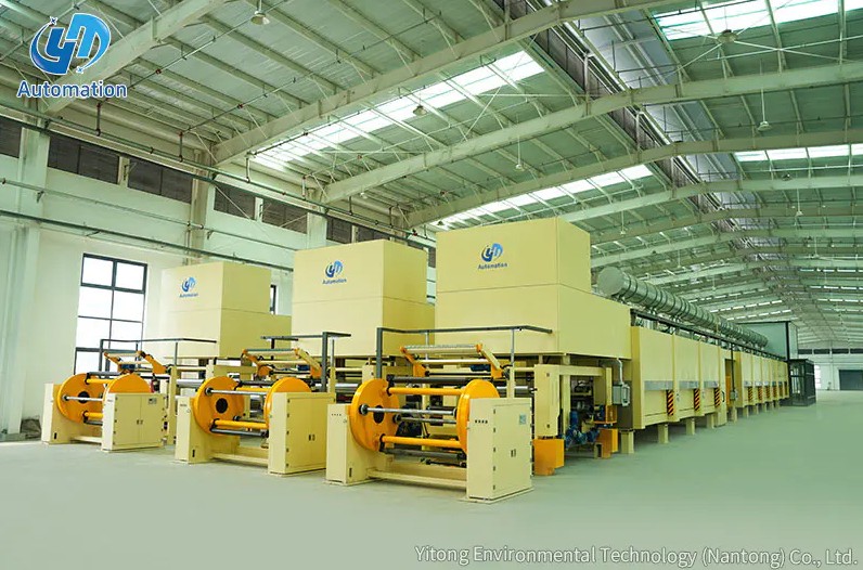
The structural integrity of a secondary coating machine is fundamental to precision manufacturing. The machine frame is typically fabricated using high-tension A3 steel plate welding combined with structural steel (type steel) processing, ensuring the entire platform remains rigid and vibration-free even during high-speed continuous operation.
A3 steel (equivalent to Q235 in Chinese standards) offers excellent weldability, moderate tensile strength (typically 370–500 MPa), and good ductility — making it an ideal base material for heavy industrial machinery frames. The welded and machined frame resists flex and thermal deformation, which is critical for maintaining alignment tolerances as tight as ±0.01 mm across the extrusion die and cooling trough system.
The robust frame design also accommodates the weight and vibration of:
One of the defining structural characteristics of a secondary coating machine is its dual-layer coating configuration. In a standard setup, the face coating is positioned at the front of the machine, and the bottom coating is positioned at the rear. This arrangement ensures that the coating is applied in a precise, layered sequence that builds up the buffer tube wall evenly and without delamination.
The face coating forms the inner surface of the buffer tube that contacts the optical fibers or gel filling compound. This layer must be chemically inert to the thixotropic filling gel and must not induce microbending stress on the fibers. Materials like PBT are commonly used here due to their low shrinkage rate and excellent dimensional stability — PBT typically exhibits a linear shrinkage of less than 0.5% after cooling, which is essential for maintaining the required excess fiber length (EFL) inside the tube.
The bottom coating forms the outer protective wall of the buffer tube and provides the mechanical properties needed for cable stranding and installation. This layer may use the same or a compatible thermoplastic material and must bond seamlessly with the face coating. The wall thickness of the bottom coating is precisely controlled — typically between 0.3 mm and 0.9 mm — depending on the cable design specification and intended deployment environment (e.g., aerial, direct burial, or duct installation).
The front-to-back arrangement of these two coating layers allows each extruder head to be individually tuned in terms of temperature profile, melt pressure, and material throughput, giving manufacturers granular control over tube geometry and mechanical performance.
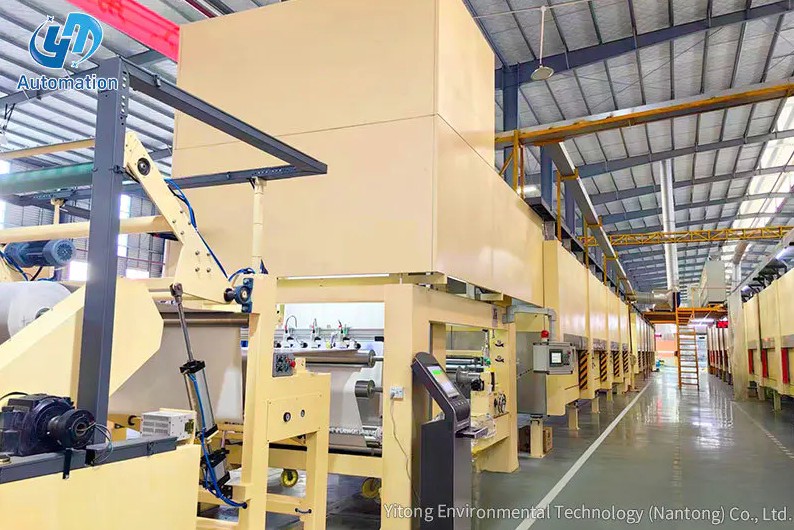
A complete secondary coating line consists of multiple integrated subsystems. Understanding each component helps manufacturers optimize production efficiency and product quality.
| Component | Function | Key Parameter |
|---|---|---|
| Fiber Payoff Unit | Supplies individual fibers under controlled tension | Tension: 30–80 g per fiber |
| Extruder (Face Coat) | Melts and delivers inner tube material | Barrel temp: 200–280°C |
| Extruder (Bottom Coat) | Melts and delivers outer tube wall material | Screw speed: 10–120 RPM |
| Gel Filling System | Injects water-blocking compound into tube core | Fill rate: synchronized with line speed |
| Extrusion Die Head | Shapes molten material around fibers into tube form | Die OD tolerance: ±0.02 mm |
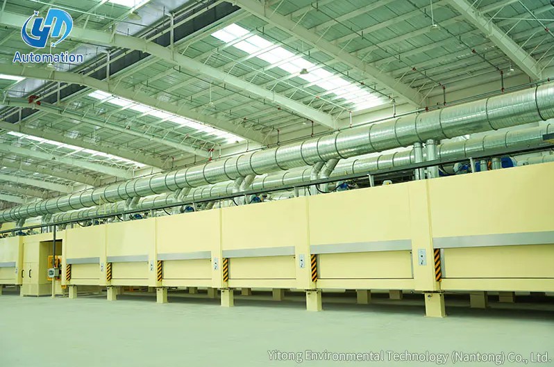
| Cooling Trough | Solidifies extruded tube via controlled water cooling | Water temp: 15–40°C (zone-controlled) |
| Capstan / Haul-off | Pulls tube at consistent speed to control dimensions | Line speed: up to 300 m/min |
| OD Measurement Gauge | Real-time non-contact tube diameter monitoring | Accuracy: ±0.001 mm |
| Takeup / Winding Unit | Winds finished loose tubes onto spools for storage | Spool capacity: 2–25 km |
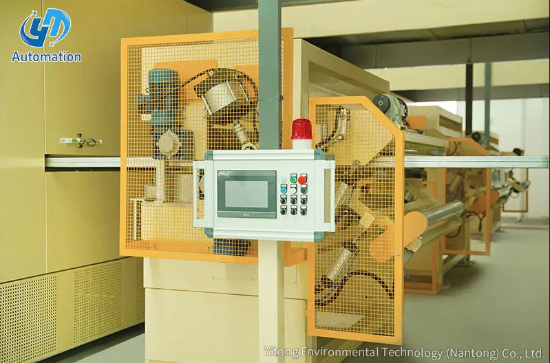
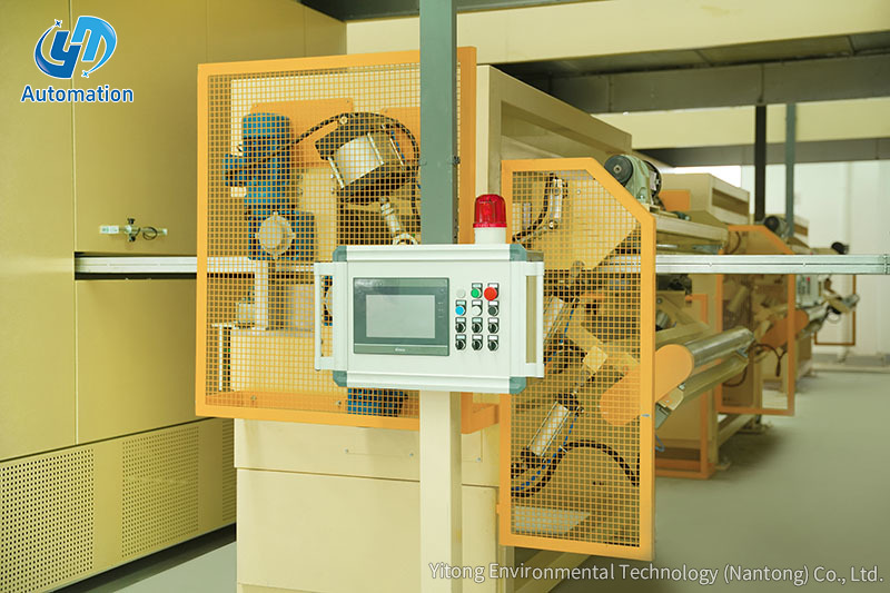
Modern machines also integrate a PLC-based control system that coordinates all subsystems in real time, enabling closed-loop feedback between the OD gauge readings and the extruder screw speed or capstan velocity to maintain dimensional tolerances automatically throughout the production run.
Secondary coating machines vary significantly in capability depending on the intended application and production volume. Below are representative technical parameters for mid-to-high-capacity machines used in commercial fiber optic cable plants:
The excess fiber length (EFL) inside the tube — a critical parameter that determines how well the cable handles tensile load without straining the fibers — is typically set between 0.2% and 0.5%, and is controlled by the ratio of fiber payoff speed to capstan line speed.
Different cable designs require different secondary coating machine configurations. The three primary types are:
Produces one buffer tube at a time and is suitable for smaller production operations or specialty cable types. These machines are simpler to operate and maintain, with investment costs typically ranging from $80,000 to $200,000 USD for a complete line.
Capable of producing multiple tubes simultaneously in parallel, significantly increasing throughput. High-volume cable manufacturers deploying millions of fiber-kilometers per year often rely on multi-tube lines to meet production targets without proportionally scaling floor space or labor.
Specifically designed to coat flat ribbon fiber stacks (4, 8, or 12 fiber ribbons) rather than individual loose fibers. The die head and cooling system are modified to accommodate the flat profile of the ribbon, and EFL control is especially critical to avoid ribbon buckling or fiber stress inside the tube.
Understanding the production process helps operators troubleshoot quality issues and optimize machine settings. Here is the standard sequence for a typical secondary coating run:
Quality in secondary coating is measured against both dimensional standards and optical performance standards. Key quality parameters include outer diameter (OD), inner diameter (ID), wall thickness eccentricity, gel fill level, and EFL. These must comply with international standards such as IEC 60794-1 and ITU-T G.652 for the finished cable.
Common quality defects and their root causes include:
Finished tubes are sampled regularly for tensile strength (typically tested at 100 N/100 mm minimum), crush resistance, and optical attenuation verification at 1310 nm and 1550 nm wavelengths.
Secondary coating machines are indispensable in the production of virtually every type of fiber optic cable used in modern telecommunications infrastructure. Key application areas include:
Global fiber optic cable deployments continue to expand rapidly, driven by 5G rollouts, hyperscale data center buildouts, and national broadband initiatives. Industry analysts project the global fiber optic cable market to exceed $20 billion USD by 2027, which directly drives sustained demand for advanced secondary coating equipment capable of high throughput and consistent quality.
Proper maintenance of a secondary coating machine ensures consistent product quality and maximizes machine uptime. Key maintenance practices include:
Operators should also conduct a full process audit whenever raw material lots change, since even minor variations in PBT pellet viscosity (MFI — Melt Flow Index) can require adjustments to temperature profiles and screw speed to maintain tube dimensional stability.
Contact Us
Recommended Products
Let’s Get In
Touch
Yitong Environmental Technology (Nantong) Co., Ltd is a manufacturer specializing in impregnation equipment.


Contact Us
Phone: 13073202297 / 13023568111
Email: [email protected] / [email protected]
Add:No.369, Nanhai Road, Tongzhou Bay, Jiangsu, China
 English
 中文简体
中文简体
 русский
 عربى
عربى