Content
A secondary coating machine works by continuously feeding primary-coated optical fibers through a precision extrusion die, where molten thermoplastic material is formed into a protective buffer tube around the fibers. The process integrates fiber tension control, dual-layer extrusion, thixotropic gel injection, water-bath cooling, and real-time dimensional monitoring into a single synchronized production line. The finished output is a dimensionally stable loose-tube buffer — the core structural element of most fiber optic cables used in telecommunications networks worldwide.
In practical terms, the machine takes in bare fibers from payoff reels at one end and delivers spooled, gel-filled, precisely dimensioned buffer tubes at the other — all at line speeds that can reach 300 meters per minute on high-performance production systems. Every parameter from melt temperature to fiber tension is monitored and adjusted in closed-loop fashion to ensure each meter of tube meets the same tight specifications.
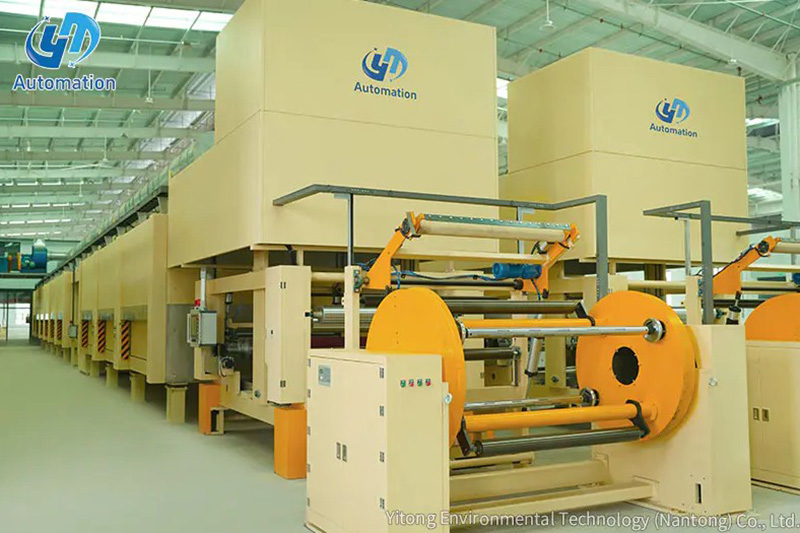
Before examining individual subsystems in detail, it helps to understand the machine as a continuous, linear process. Material and fiber enter at the upstream end and are progressively transformed as they move downstream. The sequence of operations follows this logical flow:
Each of these stages is interdependent. A change in line speed at the capstan, for example, affects tube wall thickness, fiber EFL, gel fill ratio, and cooling efficiency simultaneously — which is why modern machines rely on PLC-based closed-loop control systems rather than manually adjusted settings.
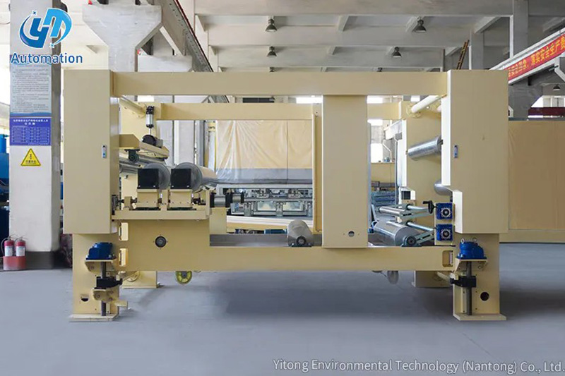
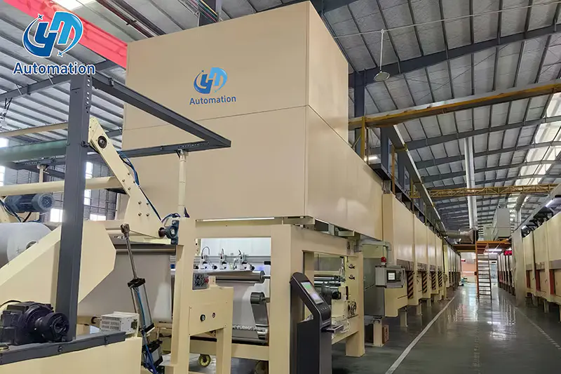
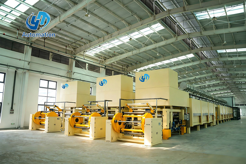
The working accuracy of a secondary coating machine begins with its physical structure. The machine frame is constructed using high-tension A3 steel plate welding combined with structural type steel processing. A3 steel (comparable to Q235 grade) provides a tensile strength of approximately 370–500 MPa, excellent weldability, and low residual stress after machining — all essential properties for a frame that must remain dimensionally stable under continuous thermal and mechanical loads.
The frame must support and align all major subsystems — extruders, cooling troughs, capstan, and takeup — to within fractions of a millimeter. Any flex or vibration in the frame translates directly into tube diameter variation or fiber position deviation inside the tube. For this reason, the welded steel structure is typically stress-relieved after fabrication and precision-machined at all critical mounting surfaces before assembly.
A production-grade secondary coating line commonly spans 15 to 30 meters in total length, and the frame must maintain alignment across this entire span even as extruder barrels heat to 250–280°C and cooling troughs operate at 15–40°C in adjacent zones. Thermal expansion joints and rigid cross-bracing are engineered into the frame design to manage these demands without compromising positional accuracy.
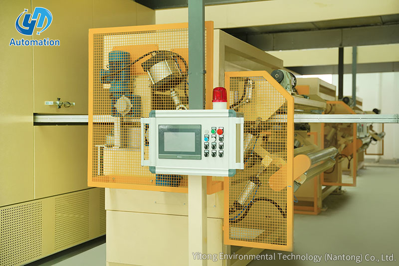
The process begins at the fiber payoff station, where spools of primary-coated optical fiber are mounted on motorized payoff cradles. Each spool may carry 20 to 25 km of fiber, and multiple spools are loaded simultaneously for multi-fiber tube production — typically 2, 4, 6, 8, 12, or 24 fibers per tube.
Fiber tension is one of the most critical parameters in secondary coating. If tension is too high, the fibers may be pre-stressed inside the finished tube, causing elevated optical attenuation. If tension is too low, fibers may tangle or form uneven loops, leading to tube geometry defects. Operating tension is typically set between 30 and 80 grams per fiber, maintained by a dancer-arm feedback system or servo-driven payoff with real-time tension measurement.
The fibers are routed through a series of ceramic or stainless steel guides that gradually converge them into the precise spacing and arrangement required at the extrusion die entry. These guides are polished to sub-micron surface roughness to avoid any scratching of the delicate primary coating on the fibers.
The extrusion system is the heart of the secondary coating machine. Most production lines use a dual-extruder configuration to apply the buffer tube material in two distinct layers. In the standard layout, the face coating extruder is positioned at the front of the machine, and the bottom coating extruder is positioned at the rear. This arrangement allows each layer to be independently controlled in terms of material type, melt temperature, and throughput rate.
The face coating extruder delivers material that forms the inner surface of the buffer tube — the surface in direct contact with the optical fibers and the filling gel. This layer must be chemically compatible with the gel compound and must exhibit very low shrinkage upon cooling to avoid inducing mechanical stress on the fibers. PBT (polybutylene terephthalate) is the predominant material choice, offering a linear mold shrinkage of less than 0.5% and a service temperature range of -40°C to +85°C.
The face coating extruder typically uses a 30 mm or 45 mm diameter single-screw with a compression ratio of 2.5:1 to 3.5:1, operating at barrel temperatures between 200°C and 270°C. The metering zone temperature is the most tightly controlled, as melt viscosity in the die must remain within a narrow window to achieve consistent wall thickness.
The bottom coating extruder applies the outer wall layer of the buffer tube, which determines the tube's external diameter and mechanical properties. This layer provides the structural strength needed for cable stranding — the tube must withstand side pressure from stranding equipment without distortion, and must maintain its circular cross-section after stranding around a central strength member.
The bottom coat layer thickness is typically between 0.3 mm and 0.9 mm, depending on cable design requirements. In some configurations, the bottom coat material may be a modified PBT compound with added UV stabilizers, colorants, or impact modifiers — enabling color-coded tube identification in multi-tube cable constructions without requiring a separate coloring pass.
The two melt streams from the face and bottom coat extruders converge at a co-extrusion die head, where they are formed concentrically around the fiber bundle. The die head consists of a fiber guide tip, a die body with two melt inlets, and a die orifice that shapes the outer diameter of the finished tube. The die orifice diameter and land length determine the tube OD and the pressure drop that drives consistent melt flow.
Die concentricity — the alignment of the die tip center with the die orifice center — must be maintained to within ±0.02 mm to prevent wall eccentricity. Most modern die heads include fine-adjustment screws or thermal centering mechanisms that allow operators to correct concentricity during production without stopping the line.
A critical function of the secondary coating process is filling the interior of the buffer tube with a thixotropic water-blocking compound — commonly referred to as filling gel or flooding compound. This gel prevents any water that enters a cable break point from traveling longitudinally through the tube and reaching sensitive splice or connector locations.
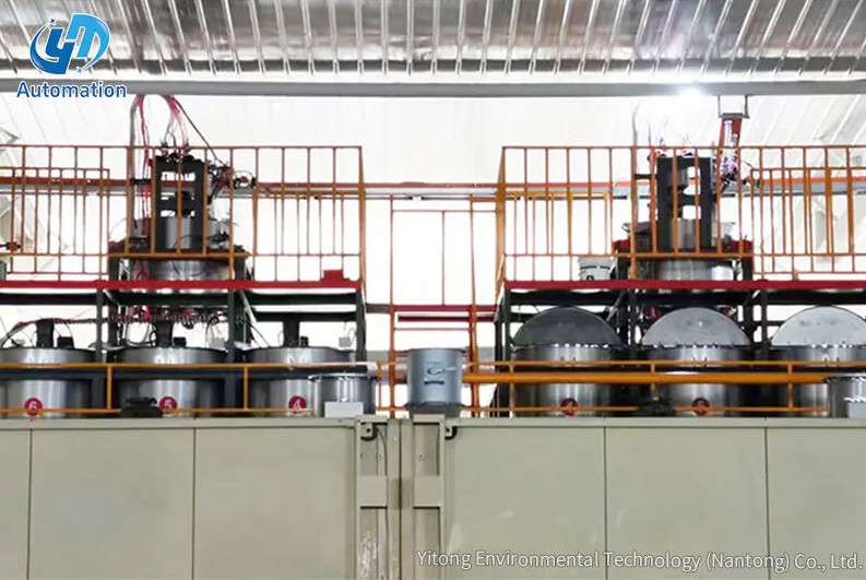
The gel filling system consists of a heated storage tank, a precision metering pump (usually a gear pump or progressive cavity pump), and a thin stainless steel injection needle that passes through the die tip and deposits gel directly inside the forming tube. The gel injection rate must be precisely synchronized with the line speed — typically expressed as a volume-per-meter ratio — to ensure complete fill without excess gel that would create back-pressure and distort the fiber arrangement.
Filling gel is maintained at an elevated temperature (typically 60–80°C) in the storage tank to reduce viscosity for pumping, but it gels to a semi-solid thixotropic state after cooling in the finished tube. This combination of flowability during filling and stability in service is what makes thixotropic gel the standard choice for loose-tube cable designs operating across the full -40°C to +70°C environmental range required by most telecommunications standards.
Immediately after the extrusion die, the freshly formed tube enters the cooling system. Cooling must be carefully controlled — too rapid a quench causes surface stress and potential cracking; too slow a cool allows the tube to sag or deform before fully solidifying, especially at high line speeds.
The cooling system on a typical secondary coating line consists of multiple water troughs arranged in series. The first trough (closest to the die) uses warm water at 40–60°C to initiate gradual cooling without thermal shock. Subsequent troughs progressively reduce the water temperature — the final troughs typically operate at 15–25°C — bringing the tube to a stable, fully solidified state before it reaches the capstan.
Total cooling trough length ranges from 6 to 15 meters depending on line speed and tube wall thickness. For a 300 m/min line producing a 2.0 mm OD tube, the tube spends only about 1.5 to 3 seconds in the cooling system — meaning the water temperature gradient across the troughs must be precisely set to achieve adequate solidification in this short window.
Each trough zone is independently temperature-controlled via a circulating water system with a heat exchanger. Operators can view and adjust each zone setpoint from the central HMI, and some advanced systems include automatic zone compensation that adjusts cooling water flow rate in response to changes in line speed.
After the cooling troughs, the tube passes through one or more non-contact laser micrometer gauges that measure its outer diameter continuously and in real time. These gauges use laser triangulation or shadow-scanning technology and can resolve diameter differences as small as ±0.001 mm at full line speed.
The OD measurement data is fed back into the PLC control system, which automatically adjusts one or more process variables to correct any drift from the target diameter:
This closed-loop feedback loop typically operates with a response time of less than one second, allowing the system to compensate for raw material viscosity variations, ambient temperature changes, or minor mechanical fluctuations without operator intervention. Modern systems maintain tube OD within ±0.03 mm of target across an entire production run of 25 km or more.
In addition to OD measurement, some advanced lines incorporate eccentricity measurement (wall thickness uniformity) using rotating gauges or X-ray systems, and fiber position detection using inline optical sensors that verify the fibers are centered within the tube rather than displaced to one side.
The capstan is the speed-governing element of the entire line. It consists of one or more motorized wheels or belts that grip the cooled tube and pull it through the machine at a precisely controlled, steady velocity. Because the capstan speed determines how fast material is drawn from the extrusion die, it directly controls both the tube's outer diameter (through the draw-down ratio) and the excess fiber length inside the tube.
Excess fiber length (EFL) is defined as the percentage by which the fiber length inside a given tube length exceeds the tube length itself. For example, an EFL of 0.3% means that for every 1,000 meters of tube, the fiber inside is 1,003 meters long. This small surplus of fiber is essential: it allows the cable to sustain tensile loads without the fibers themselves experiencing strain, which would increase optical attenuation.
EFL is set by the ratio of fiber payoff speed to capstan speed:
EFL values for standard loose-tube cables typically fall between 0.2% and 0.5%, with tighter tolerances required for cables intended for direct-burial or submarine applications where thermal cycling and mechanical loading are more severe.
All the subsystems described above — payoff tension, extruder temperature and speed, gel pump rate, cooling water temperature, OD gauge feedback, and capstan speed — are coordinated by a central programmable logic controller (PLC) system. The operator interacts with this system through a touchscreen HMI (Human-Machine Interface) that displays real-time process data, alarm conditions, and trend graphs.
Key PLC control functions include:
Advanced systems may also integrate with factory-level MES (Manufacturing Execution Systems) to report production volumes, material consumption, and quality data in real time to plant management software.
Understanding how the key process parameters interact is essential for operators who need to troubleshoot quality problems or optimize production efficiency. The table below summarizes the most important parameter-to-output relationships:
| Process Parameter | If Too High | If Too Low | Target Range (Typical) |
|---|---|---|---|
| Extruder barrel temperature | Polymer degradation, discoloration | High melt pressure, surface roughness | 200–280°C (PBT) |
| Capstan line speed | Thin wall, reduced OD, low EFL | Thick wall, high OD, excess EFL | 40–300 m/min |
| Fiber payoff tension | Fiber pre-stress, attenuation increase | Fiber tangling, tube deformation | 30–80 g per fiber |
| Gel injection rate | Back-pressure, fiber displacement | Incomplete fill, moisture ingress risk | Synchronized to line speed (ml/m) |
| Cooling water temperature | Incomplete solidification, tube sag | Thermal shock, surface cracking | 15–60°C (graded zones) |
| Screw rotation speed | Overheating, melt degradation | Inadequate throughput, OD drop | 10–120 RPM |
Operators who deeply understand these interactions can solve most quality deviations by adjusting a single parameter rather than making multiple changes simultaneously — which is the fastest path to restoring stable, on-specification production.
The final stage of the secondary coating process is winding the finished buffer tube onto takeup reels for storage and downstream processing. The takeup system must apply a controlled, consistent tension to the tube during winding to prevent deformation or fiber stress from uneven spool pressure.
The traverse mechanism on the takeup reel lays the tube in even, overlapping layers across the reel flange width, preventing any localized pressure points that could indent the tube wall and alter the geometry of the fibers inside. Reel capacity typically ranges from 2 km to 25 km of finished tube depending on tube diameter and reel size.
When a reel is full, the machine performs a spool changeover — either manually or automatically. During this brief changeover, a length of tube that cannot be wound onto either the full or new reel is typically cut and discarded as a production transition piece. Minimizing changeover transition length is an important efficiency metric for high-volume cable manufacturers, since it directly affects material yield per reel.
Each completed reel is labeled with production data — tube specification, reel length, production date, and OD measurement log — and transferred to the stranding area, where multiple buffer tubes will be assembled around a central strength member to form the complete fiber optic cable.
The working sequence of a secondary coating machine is not limited to steady-state production — the startup and shutdown phases are equally important and require systematic attention to avoid scrap generation and equipment damage.
Even well-maintained secondary coating lines encounter recurring operational challenges. Understanding the root causes behind the most common problems allows production teams to resolve them efficiently.
Contact Us
Recommended Products
Let’s Get In
Touch
Yitong Environmental Technology (Nantong) Co., Ltd is a manufacturer specializing in impregnation equipment.


Contact Us
Phone: 13073202297 / 13023568111(WhatsApp/Wechat)
Email: [email protected] / [email protected]
Add:No.369, Nanhai Road, Tongzhou Bay, Nantong, Jiangsu, China


 English
 中文简体
中文简体
 русский
 عربى
عربى